
ASTM D256 – Izod Pendulum Impact Resistance of Plastics
A complete lab guide to notched Izod impact testing of plastics: test methods A–E, specimen and notch geometry, pendulum selection, conditioning, procedure, J/m calculation, and how ASTM D256 compares with ISO 180 (and the BIS IS 13360 series) — supported by FITCO India's mechanical testing programme.
Overview & scope
ASTM D256 is the American standard covering the determination of the Izod pendulum impact resistance of rigid and semi-rigid plastics. Maintained by ASTM Committee D20 on Plastics, it measures the energy a notched (or, in the reversed-notch variant, an effectively unnotched) bar absorbs when fractured by a single swing of a calibrated pendulum hammer. It is one of the most widely cited toughness references for compounders, moulders, masterbatch producers, and NABL / ISO 17025-accredited laboratories across India.
The result describes a material's resistance to sudden shock and its notch sensitivity — properties that tensile and flexural tests do not capture. Impact resistance is reported as energy absorbed per unit width of the notch, in J/m (or ft·lbf/in).
Tip: ASTM D256 is a comparative, geometry-dependent test. A D256 value is only meaningful alongside the test method letter, notch radius, specimen thickness, and temperature — quote all of them in every report.
What does it measure?
The kinetic energy lost by the pendulum in breaking the specimen, normalised to the notch width, giving notched Izod impact resistance (J/m). It does not measure tensile, flexural, or fatigue behaviour — see ASTM D638, ASTM D790, and the relevant fatigue methods respectively. The Charpy (three-point, simply supported) configuration is covered separately by ASTM D6110, not D256.
Sample materials
ABS, polycarbonate (PC), PC/ABS blends, nylon (PA6, PA66), impact-modified polypropylene copolymers, HDPE, high-impact polystyrene (HIPS), POM, glass-fibre reinforced compounds, and recycled / compounded grades qualified for impact performance.
Latest edition
Refer to the current ASTM D256 revision on astm.org and confirm the edition cited in your customer specification, as the procedures and toss-correction guidance have been refined across revisions.
Industries & applications
Automotive & mobility
Bumpers, interior trim, battery housings, and impact-modified compounds where cold-temperature toughness governs OEM approval.
Packaging & FMCG
Crates, closures, and rigid containers that must survive drop and handling shocks across the supply chain.
Electrical & appliances
Switchgear, enclosures, and housings where brittle failure under impact is a safety and warranty risk.
Polymer compounding
Impact-modifier dosing, masterbatch, and recyclate QC — Izod resistance flags embrittlement before it reaches production.
Test methods A–E
ASTM D256 contains several procedures. Method A (notched Izod) is by far the most common; the other procedures address low-energy materials, notch sensitivity, and tougher grades that resist a standard notched break.
| Method | Configuration | When to use |
|---|---|---|
| A | Notched Izod, cantilever beam | Default — general notched impact resistance of most plastics |
| C | Notched Izod with toss correction | Low-energy materials (typically below ~27 J/m) where energy to toss the broken piece is significant |
| D | Notched, two notch radii | Quantifying a material's notch-radius sensitivity |
| E | Reversed-notch Izod | Tough grades that will not break with the notch facing the striker; approximates unnotched behaviour |
Tip: Methods A and C produce numerically different values for the same material because Method C subtracts the toss energy. Never compare an A result against a C result directly.
Specimen & notch geometry
The standard Izod bar is a rectangular cross-section moulded or machined to defined dimensions, with a single 45° notch milled into one long face. The notch is the most critical — and most error-prone — feature of the whole test.
| Parameter | Value | Notes |
|---|---|---|
| Specimen length | 63.5 mm (2.5 in) | Standard bar length |
| Specimen depth (width) | 12.7 mm (0.5 in) | Dimension into which the notch is cut |
| Thickness | 3.2–12.7 mm | 3.2 mm (1/8 in) common; 6.4 mm preferred for bars prone to bending/crushing |
| Notch angle | 45° | Single notch on one face |
| Notch radius | 0.25 ± 0.05 mm (0.010 in) | Tip radius controls the stress concentration |
| Depth under notch | 10.16 mm (0.4 in) | Remaining material below the notch (12.7 − 2.54 mm) |
Tip: A blunt or chipped notch cutter is the single biggest source of false-high impact values. Inspect the notch tip under magnification and re-sharpen or replace cutters on a fixed schedule.
Specimen preparation
- Injection-mould or machine bars to the chosen thickness with smooth, defect-free faces and parallel edges.
- Notch each bar with a single-tooth milling or broaching cutter set to a 45° angle and a 0.25 mm tip radius, leaving 10.16 mm of material under the notch.
- Inspect every notch for tip radius, depth, and freedom from chatter marks; discard bars with damaged or off-spec notches.
- Condition specimens at 23 °C ± 2 °C and 50% ± 5% RH for at least 40 hours per ASTM D618, unless the material specification states otherwise.
- For sub-ambient or elevated-temperature testing, bring specimens to the target temperature in a conditioning chamber and test quickly to limit drift.
Apparatus & pendulum selection
- Pendulum impact tester with a rigid base, vertical specimen vise (clamp), and an interchangeable Izod striker swinging in a calibrated arc.
- Multiple pendulum capacities (for example 1, 2.7, 5.5, 11, and 22 J) so the energy absorbed falls in a reliable mid-range — commonly between about 10% and 85% of the pendulum's capacity.
- Notch cutter capable of holding the 45° angle and 0.25 mm tip radius repeatably; this is part of the measurement system, not just sample prep.
- Friction and windage correction so the free-swing energy loss of the pendulum is accounted for in every result.
- Digital encoder / software to read absorbed energy, apply toss correction (Method C), and log specimen dimensions and conditions for traceability.
Tip: Choosing too large a pendulum compresses ductile breaks into the bottom of the scale and inflates scatter. If absorbed energy is below ~10% of capacity, drop to a smaller pendulum and retest.
Test procedure
- Record material identity, batch, conditioning, temperature, humidity, and the test method letter (A, C, D, or E).
- Select a pendulum so the expected break falls in the reliable mid-range; verify free-swing friction/windage and zero the energy reading.
- Clamp the specimen vertically in the vise with the notch facing the striker (or away from it for reversed-notch Method E), the notch aligned to the top of the clamp.
- Release the pendulum from its fixed start position and let it break the specimen in a single swing.
- Read the absorbed energy; apply the toss correction for Method C.
- Record the break type (complete, hinge, partial, or non-break) — non-breaks are reported, not averaged in as a number.
- Repeat across the specimen set, then compute impact resistance and statistics.
Calculations & outputs
- Izod impact resistance: energy absorbed (J) divided by the specimen width at the notch (m), giving J/m (or ft·lbf/in).
- Toss correction (Method C): subtract the energy used to throw the broken fragment from the gross absorbed energy.
- Statistics: report mean, standard deviation, and coefficient of variation for the specimen set.
- Break type: classify each result (complete / hinge / partial / non-break) — essential context for the number.
Example: a 3.2 mm-thick specimen absorbs 0.80 J. Impact resistance = 0.80 J / 0.0032 m = 250 J/m. The same energy on a thinner or thicker bar gives a different J/m value, which is why thickness must always be reported.
Factors affecting results
- Notch quality: tip radius, depth, and surface finish dominate the result; a sharper-than-spec notch reads low, a blunt notch reads high.
- Temperature: many plastics show a sharp ductile-to-brittle transition, so cold testing can collapse impact resistance — test at the service-relevant temperature.
- Moulding history: orientation, weld lines, and residual stress shift impact values batch to batch.
- Conditioning: moisture in hygroscopic polymers such as nylon strongly affects toughness.
- Pendulum range: using a capacity mismatched to the break energy widens scatter.
ASTM D256 vs ISO 180 — key differences
ISO 180 is the international Izod analogue. Both swing a pendulum at a notched bar, but specimen size, notch options, and the reported unit differ, so values are not directly comparable. India's BIS equivalent, IS 13360 (Part 5/Sec 4), is technically identical to ISO 180 — useful when an Indian customer specification cites the IS series.
| Parameter | ASTM D256 | ISO 180 |
|---|---|---|
| Primary market | Americas, global OEM | Europe, Asia, global OEM |
| Typical specimen | 63.5 × 12.7 × 3.2 mm | 80 × 10 × 4 mm |
| Notch radius | 0.25 mm | Types A 0.25 mm, B 1.0 mm, C 0.10 mm |
| Reported unit | J/m (energy per notch width) | kJ/m² (energy per area under notch) |
| Conditioning reference | ASTM D618 | ISO 291 |
| India BIS equivalent | — | IS 13360 (Part 5/Sec 4) |
Tip: Because ASTM reports J/m and ISO reports kJ/m², you cannot simply convert one to the other — the normalising dimension is different. Run the method your specification cites.
Recommended lab setup
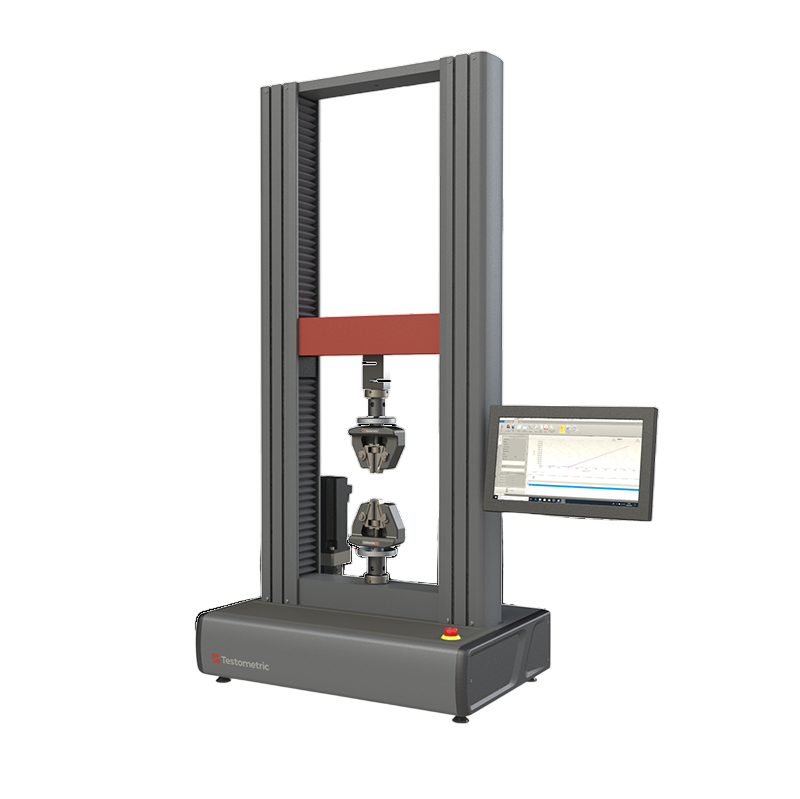
Impact testing rarely stands alone — Izod results are read alongside tensile (ASTM D638) and flexural (ASTM D790) data to characterise a plastic fully. FITCO India helps you build that complete mechanical lab, pairing pendulum impact apparatus with Testometric (UK) universal testing machines for the companion strength and modulus tests.
Impact frame
Pendulum impact tester with interchangeable Izod strikers and a range of pendulum capacities for low- to high-energy breaks.
Notching
Precision motorised notch cutter holding the 45° angle and 0.25 mm tip radius for repeatable, in-spec notches.
Companion UTM
Testometric X-Series (X250/X350/X500) for ASTM D638 tensile and ASTM D790 flexural characterisation on the same materials.
Software & reporting
Digital energy capture with toss correction, plus Testometric WinTest Analysis for audit-ready tensile/flexural reports.
- A coordinated mechanical lab — impact, tensile, and flexural — specified to your material mix and standards.
- Testometric UTMs with ±0.5% load accuracy and a 1–500 mm/min speed range for D638 and D790 on one frame.
- Installation, operator training, calibration support, spares, and after-sales backing across India.
Configurations vary by material range and throughput; contact FITCO India for a setup tuned to ASTM D256 and its companion mechanical standards.
FAQs
What does ASTM D256 actually measure?
The energy a notched plastic bar absorbs when broken by a single pendulum swing, reported as impact resistance per unit notch width in J/m.
Why is the notch so important?
The 45° / 0.25 mm-radius notch sets the stress concentration. A blunt or chipped notch reads artificially high, so cutter condition is part of the measurement system.
When do I use Method C instead of Method A?
Method C is for low-energy materials (roughly below 27 J/m), where the energy used to toss the broken fragment is significant and must be corrected.
Is ASTM D256 the same as ISO 180?
No. They use different specimen sizes and report different units (J/m vs kJ/m²), so values are not directly comparable. India's IS 13360 (Part 5/Sec 4) matches ISO 180.
What about Charpy impact?
The Charpy (simply supported) configuration is covered by ASTM D6110, not D256. D256 is the cantilever Izod method.
How many specimens should I test?
Test at least five, or ten for variable or anisotropic materials, and report break type and statistics with the mean.
Related Standards
ASTM D638
Tensile properties of plastics — pair with D256 for strength plus toughness.
ASTM D790
Flexural properties of plastics — completes the core mechanical profile alongside impact.
ASTM D695
Compressive properties of rigid plastics — another sibling mechanical method.
Need Help with ASTM D256 Izod Impact Testing?
Our experts can help you build a coordinated mechanical lab — pendulum impact apparatus plus Testometric UTMs for tensile and flexural testing — matched to your plastics and the standards you report against.