
ASTM D695 – Compressive Properties of Rigid Plastics
A complete lab guide to compression testing of rigid plastics and high-modulus composites: specimen geometry, slenderness ratio, the support jig for thin materials, platen alignment, crosshead speed, modulus calculation, and compliant reporting – engineered around Testometric UK universal testing machines and supported by FITCO India.
Overview & scope
ASTM D695 is the primary American standard for determining the compressive properties of unreinforced and reinforced rigid plastics, including high-modulus composites, when loaded in compression at relatively low, uniform rates of straining or loading. It is maintained by ASTM Committee D20 on Plastics and is widely cited in material datasheets, OEM specifications, and NABL/ISO 17025-accredited laboratory scopes across India.
The standard reports compressive strength, compressive yield strength, modulus of elasticity in compression, and deformation beyond the yield point for rigid plastics tested between parallel platens under controlled speed and environment.
Tip: ASTM D695 is intended for rigid plastics. Materials that merely flatten under load without fracturing or yielding do not exhibit a compressive strength by this method — report yield or stress at a stated strain instead.
What does it measure?
Compressive strength (MPa), compressive yield strength (MPa), compressive modulus of elasticity (MPa or GPa), and deformation beyond yield. It does not measure tensile or flexural behaviour — see ASTM D638 and ASTM D790 respectively, which together with D695 complete the core mechanical characterisation of a rigid plastic.
Sample materials
Rigid PVC, polycarbonate (PC), nylon (PA6, PA66), POM/acetal, PEEK, epoxy and phenolic thermosets, glass-fibre reinforced compounds, laminates, and high-modulus polymer-matrix composites — including machined stock shapes used in bearings, bushes, and structural components.
India context & equivalents
The international counterpart is ISO 604, which the Bureau of Indian Standards has adopted identically as IS 13360 (Part 5/Sec 8). Indian laboratories serving both export and domestic specifications routinely run ASTM D695 and ISO 604 / IS 13360 methods on the same universal testing machine with the appropriate fixtures and software templates.
Industries & applications
Engineering plastics & stock shapes
Bearings, bushes, gears, wear pads, and seals machined from PA, POM, and PEEK — compressive strength and modulus drive load-bearing approvals.
Electrical & insulation
Laminates, switchgear components, and insulating boards where compressive integrity under clamping loads is specified.
Composites & aerospace
High-modulus polymer-matrix composites — D695 with the support jig is a long-established route for compressive strength of thin laminates.
Construction & infrastructure
Rigid PVC profiles, GRP components, and structural foams used in load-bearing building and pipeline applications across India.
Specimen geometry & dimensions
The standard specimen is a right cylinder or prism whose length is twice its principal width or diameter. Slender column specimens with a higher slenderness ratio are used when compressive modulus or accurate stress–strain data are required, and thin sheet materials are tested as jig-supported specimens.
| Specimen form | Typical dimensions (mm) | Slenderness ratio | Typical use |
|---|---|---|---|
| Prism (preferred) | 12.7 × 12.7 × 25.4 | ~2:1 length-to-width | Default — compressive strength of rigid plastics |
| Cylinder | Ø 12.7 × 25.4 long | ~2:1 length-to-diameter | Moulded or machined round stock |
| Slender column | Length set by material | 11:1 to 16:1 | Compressive modulus and yield determination |
| Thin sheet (jig-supported) | Material < 3.2 mm thick | Supported by jig | Sheet, laminates, and thin composites in the D695 support jig |
Tip: Test at least five specimens for isotropic materials and ten (five normal, five parallel to the principal axis) for anisotropic materials — and always state the specimen form in the report, because results from different geometries are not directly comparable.
Specimen preparation
- Prepare specimens by moulding to size or by machining from sheet, rod, or finished parts with smooth, defect-free surfaces.
- Machine the loaded end faces flat, parallel to each other, and perpendicular to the long axis — out-of-square ends are the most common cause of scattered results.
- Inspect for voids, sink marks, machining chatter, and edge defects; discard any specimen with visible flaws.
- Condition at 23°C ± 2°C and 50% ± 10% RH for a minimum of 40 hours per ASTM D618 unless the material specification states otherwise.
- Measure width and thickness (or diameter) at several points with a calibrated micrometer and compute the minimum cross-sectional area for stress calculations.
Platens, subpress & support jig
- Hardened parallel platens — flat, polished compression platens with one self-aligning (spherically seated) face keep loading uniform across the specimen ends.
- Compression subpress / cage — a guided two-platen tool that maintains platen parallelism and axial alignment, recommended for small block and cylinder specimens.
- D695 support jig — for materials under 3.2 mm thick, the standard specifies a slotted support jig that restrains the thin specimen against buckling so it fails in true compression.
- Centre the specimen on the platen axis; off-centre loading introduces bending and depresses both strength and modulus.
Instrumentation & strain measurement
- Compressometer or strain measurement is required for modulus. Raw crosshead displacement includes machine, platen, and seating compliance and overstates deformation at low strain.
- Use a clip-on compressometer/extensometer spanning the specimen gauge region, or a non-contact video extensometer tracking marks on the column faces.
- Select a load cell so peak force falls between 10% and 90% of rated capacity — reinforced grades can exceed 100 kN on full-size specimens, so check capacity before testing.
- Sample at ≥ 20 Hz; brittle thermosets can fail abruptly and need fast acquisition to capture peak load.
Test procedure
- Record temperature, humidity, material identification, and specimen form for the batch.
- Verify current load cell and strain-device calibration; zero both channels.
- Measure and log specimen dimensions; mount the specimen centrally between the platens (or in the subpress / support jig for thin materials).
- Bring the platens into light contact without pre-loading the specimen.
- Run at a crosshead speed of 1.3 ± 0.3 mm/min and record the full force–deformation curve.
- Continue loading until yield or fracture, or to the deformation limit given in the governing specification.
- Reject results from specimens that buckle, broom at the ends, or fail from visible defects, and repeat on fresh specimens.
- Export compressive strength, yield, and modulus with the curve for traceability.
Calculations & outputs
- Compressive stress: σ = F / A₀ — force divided by the original minimum cross-sectional area, in MPa.
- Compressive strength: the maximum compressive stress sustained by the specimen (at or before fracture).
- Compressive yield strength: the stress at the first point on the stress–strain curve where strain increases without an increase in stress.
- Modulus of elasticity: the slope of the initial linear portion of the compressive stress–strain curve, requiring instrumented strain data.
Example: a 12.7 × 12.7 mm prism has A₀ = 161.3 mm². At a peak force of 14,500 N, compressive strength = 14500 / 161.3 ≈ 90 MPa.
Crosshead speed guidance
- 1.3 ± 0.3 mm/min — the standard crosshead speed for ASTM D695 compression testing.
- As specified — always follow the governing material or OEM specification and document the actual speed in every report.
Tip: Plastics are strain-rate sensitive in compression just as in tension — a result reported without the test speed and specimen geometry cannot be compared across laboratories.
Reporting requirements
- Material identification, grade, lot/batch number, and moulding or machining method.
- Specimen form, individual dimensions, cross-sectional area, and number tested (with any rejected specimens and reasons).
- Conditioning, test temperature and humidity, crosshead speed, fixture type (platens, subpress, or support jig), and strain-measurement device.
- Results with statistics: compressive strength, yield strength, modulus (mean, SD, CV%), and the failure mode observed.
ASTM D695 vs ISO 604 — key differences
Both standards measure compressive properties of plastics but use different specimen geometries and speeds, so results are not directly numerically comparable. ISO 604 is adopted in India as IS 13360 (Part 5/Sec 8). Select the standard cited by your customer or target market.
| Parameter | ASTM D695 | ISO 604 / IS 13360 (Pt 5/Sec 8) |
|---|---|---|
| Primary market | Americas, global OEM | Europe, Asia, BIS/Indian specifications |
| Strength specimen | 12.7 × 12.7 × 25.4 mm prism or Ø12.7 × 25.4 mm cylinder | 10 × 10 × 4 mm |
| Modulus specimen | Slender column, slenderness ratio 11:1–16:1 | 50 × 10 × 4 mm |
| Thin materials | Support jig for < 3.2 mm thickness | Geometry adapted per the standard |
| Conditioning reference | ASTM D618 | ISO 291 |
| Typical speed | 1.3 ± 0.3 mm/min | Lower speed for modulus, higher for strength, per material |
Tip: If a specification simply says "compression test," confirm ASTM D695 or ISO 604 before machining specimens — the geometries differ and archived data will not be comparable.
Recommended Testometric setup
Frame
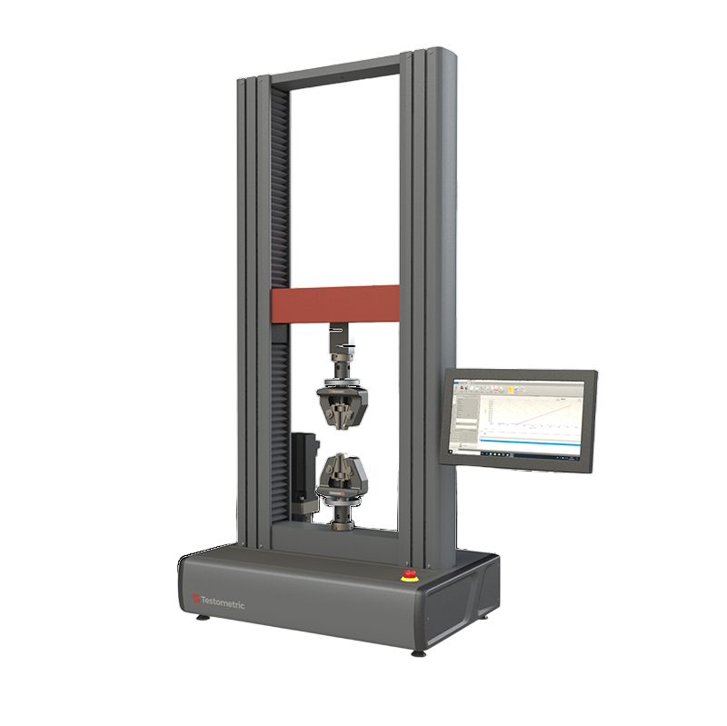
Testometric X-Series (X350/X500) twin-column UTM, or XFS floor-standing frames for high-force reinforced compounds, with precise low-speed crosshead control at 1.3 mm/min.
Fixtures
Hardened self-aligning compression platens, guided compression cage/subpress, and the ASTM D695 support jig for thin sheet and laminates.
Strain measurement
Clip-on compressometer or non-contact video extensometer integrated with WinTest Analysis for instrumented compressive modulus.
Software
WinTest Analysis with ASTM D695 and ISO 604 method templates, automatic yield and modulus detection, batch statistics, and audit-ready PDF/CSV exports.
- ±0.5% load accuracy and 0.000001 mm position resolution for tight modulus reporting at low strain.
- Stable low-speed control at 1.3 mm/min with the same frame covering tensile, flexural, and compression methods.
- 900+ grip and accessory options including platens, cages, jigs, and video extensometry.
- Run ASTM D695 and ISO 604 / IS 13360 methods on one machine with switchable software templates.
- FITCO India support: installation, operator training, spares, after-sales, and 2-year comprehensive warranty.
Model suggestions for compression testing
| X-Series model | Force capacity | Typical use |
|---|---|---|
| X350-10 | 10 kN | Unfilled rigid plastics (PVC, PC, POM) |
| X500-50 | 50 kN | Engineering plastics and filled compounds |
| XFS series | Higher capacities | High-modulus composites and reinforced laminates |
Specifications vary by configuration; contact FITCO India for a tuned method and accessories aligned to ASTM D695.
FAQs
What specimen size does ASTM D695 use?
The preferred specimen is a 12.7 × 12.7 × 25.4 mm prism or a Ø12.7 × 25.4 mm cylinder — a right prism or cylinder whose length is twice its principal width or diameter. Slender columns (slenderness ratio 11:1–16:1) are used for modulus.
Can I report compressive modulus without a strain device?
No. Crosshead displacement includes machine, platen, and seating compliance, which distorts low-strain data. Use a compressometer or video extensometer for valid modulus.
How are thin sheets tested in compression?
Materials under 3.2 mm thick are tested in the D695 support jig, which restrains the specimen against buckling so it fails in true compression rather than by instability.
What test speed does ASTM D695 specify?
A crosshead speed of 1.3 ± 0.3 mm/min, maintained until yield, fracture, or the deformation limit in the governing specification.
Is ASTM D695 the same as ISO 604?
They measure the same properties but use different specimen geometries and speeds, so values are not directly comparable. ISO 604 is adopted in India as IS 13360 (Part 5/Sec 8); use the standard your specification cites.
How many specimens are required?
At least five for isotropic materials, and ten for anisotropic materials (five normal and five parallel to the principal axis).
Related Standards
ASTM D638
Tensile properties of plastics — pair with D695 for full mechanical characterisation.
ASTM D790
Flexural properties of plastics — the third leg of the core mechanical property set.
ISO 178
Flexural properties of plastics by the ISO route — common in BIS-aligned specifications.
Need Help with ASTM D695 Compression Testing?
Our experts can help you select the right Testometric UTM configuration, compression platens, subpress, and support jig for your rigid plastics and composites testing requirements.