ASTM D790 – Flexural Properties of Plastics
A complete lab guide to the 3-point bend test for unreinforced and reinforced plastics: specimen geometry, 16:1 span, loading-nose radius, Procedures A and B, flexural strength and modulus calculation, and compliant reporting – engineered around Testometric UK universal testing machines and supported by FITCO India.
Overview & scope
ASTM D790 defines the test methods for determining the flexural properties of unreinforced and reinforced plastics and electrical insulating materials using a three-point bending configuration. It is maintained by ASTM Committee D20 on Plastics and is a core QC and material-qualification reference for moulders, compounders, and NABL/ISO 17025-accredited laboratories across India.
The test reports flexural strength, flexural modulus, and stress at a defined strain, characterising how a rigid plastic resists bending — a property closely tied to part stiffness in service.
Tip: ASTM D790 covers three-point bending. For four-point loading (where peak stress is distributed over a central region), use ASTM D6272 instead.
What does it measure?
Flexural strength (MPa), flexural modulus of elasticity (MPa or GPa), and flexural stress at 5% strain for ductile materials that do not break. It does not measure tensile or impact behaviour — see ASTM D638 and ASTM D256.
Sample materials
Polypropylene (PP), ABS, polycarbonate (PC), nylon (PA6/PA66), POM, PBT, glass-fibre reinforced compounds, thermosets, and electrical insulating laminates — including recycled and compounded grades for incoming QC.
Industries & applications
Automotive & mobility
Structural and trim mouldings where stiffness and load-bearing performance are specified by the OEM.
Electrical & electronics
Insulating laminates and housings — flexural modulus governs rigidity under mounting loads.
Polymer compounding
Glass-fibre and filler loading is verified quickly via flexural modulus shifts in QC.
Consumer & appliances
Rigid components and panels where bending stiffness drives perceived quality and durability.
Specimen & fixture geometry
The standard bar specimen is moulded or machined with smooth, parallel faces. The support span is set to 16 times the specimen depth (16:1) unless the material requires an adjusted ratio.
| Parameter | Typical value | Note |
|---|---|---|
| Specimen length | ~127 mm | 125–200 mm depending on thickness/modulus |
| Specimen width (b) | 12.7 mm | Measure at the midspan |
| Specimen depth (d) | 3.2 mm | 3.2–6.4 mm range |
| Support span (L) | ~51 mm | 16 × depth for a 3.2 mm bar |
| Loading-nose radius | 5 mm ± 0.1 mm | Central loading nose |
| Support radius | 5 mm typical | Both supports equal |
Tip: Always recompute and reset the span when the specimen thickness changes — using the wrong span is the most common cause of non-comparable flexural data between batches.
Specimen preparation
- Mould or machine bars with smooth, defect-free surfaces and parallel faces; deburr cut edges.
- Inspect for sink marks, voids, and weld lines in the central span — discard defective specimens.
- Condition at 23°C ± 2°C and 50% ± 5% RH per ASTM D618 unless the specification states otherwise.
- Measure width and depth at the midspan with a calibrated micrometer (≤ 0.01 mm).
- Test at least five specimens; use ten for anisotropic or highly variable materials.
Fixture & instrumentation
- Use a rigid three-point bend fixture with a central loading nose (5 mm radius) and two adjustable supports of equal radius.
- Select a load cell so peak force falls between 10% and 90% of rated capacity for best resolution.
- Measure midspan deflection from crosshead travel for modulus, or use a deflectometer for higher accuracy on stiff materials.
- Sample at a rate sufficient to capture the peak cleanly, especially for brittle or filled compounds.
Test procedure (Procedures A & B)
ASTM D790 defines two procedures distinguished by strain rate. Procedure A (0.01 mm/mm/min) is preferred and used for both modulus and strength. Procedure B (0.10 mm/mm/min) is used for flexural strength when a material does not break by 5% strain under Procedure A.
- Record temperature, humidity, and specimen identification.
- Verify load-cell calibration; set and confirm the 16:1 support span for the measured depth.
- Centre the specimen on the supports with the loading nose at midspan; zero load and position.
- Apply load at the crosshead rate computed for Procedure A (or B), recording the full load–deflection curve.
- Continue to break, or to 5% strain for ductile materials, per the selected procedure.
- Export flexural strength, modulus, and stress at 5% strain with the curve for traceability.
| Aspect | Procedure A | Procedure B |
|---|---|---|
| Strain rate (Z) | 0.01 mm/mm/min | 0.10 mm/mm/min |
| Primary use | Modulus & strength (preferred) | Flexural strength only |
| When to use | Default for most materials | Materials that don't break by 5% strain under A |
Calculations & outputs
- Flexural stress: σ = 3PL / (2bd²) — P = load, L = support span, b = width, d = depth. Result in MPa.
- Flexural strain: ε = 6Dd / L² — D = midspan deflection.
- Flexural modulus (tangent): E_B = L³m / (4bd³) — m = slope of the initial linear region of the load–deflection curve.
- Crosshead rate: R = Z L² / (6d) — Z = 0.01 (Procedure A) or 0.10 (Procedure B) mm/mm/min.
Example (L = 51 mm, b = 12.7 mm, d = 3.2 mm): at P = 100 N, flexural stress = (3 × 100 × 51) / (2 × 12.7 × 3.2²) = 15,300 / 260.1 = 58.8 MPa. Procedure A crosshead rate = (0.01 × 51²) / (6 × 3.2) = 1.35 mm/min.
Crosshead rate guidance
- Always compute the crosshead rate from R = ZL²/(6d) for the actual span and depth — it is not a fixed value.
- Procedure A uses Z = 0.01 mm/mm/min; Procedure B uses Z = 0.10 mm/mm/min.
- Document the procedure, span, and computed rate in every report.
Tip: Reporting a flexural result without the span ratio and procedure makes it impossible to compare across labs — both materially change the measured values.
Reporting requirements
- Material identification, grade, lot/batch number, and preparation method.
- Specimen dimensions, support span and span ratio, number tested, and any rejected specimens with reasons.
- Conditioning, temperature and humidity, procedure (A or B), and computed crosshead rate.
- Results with statistics: flexural strength, flexural modulus, stress at 5% strain (mean, SD, CV%).
ASTM D790 vs ISO 178 — key differences
Both determine flexural properties in three-point bending, but specimen size and rate conventions differ, so results are not directly numerically comparable. Use the standard cited by your customer or market.
| Parameter | ASTM D790 | ISO 178 |
|---|---|---|
| Primary market | Americas, global OEM | Europe, Asia, global OEM |
| Typical specimen | 127 × 12.7 × 3.2 mm | 80 × 10 × 4 mm |
| Span ratio | 16:1 (adjustable) | 16:1 (span 64 mm for 4 mm bar) |
| Rate basis | Strain rate via R = ZL²/6d | Fixed test speed (e.g. 2 mm/min) |
| Conditioning | ASTM D618 | ISO 291 |
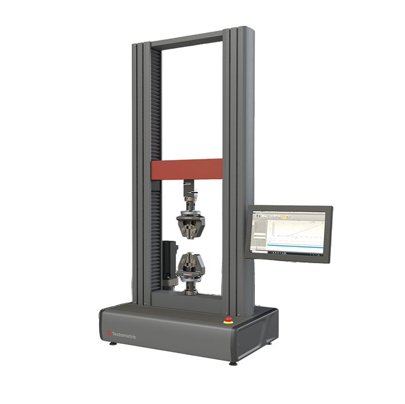
Recommended Testometric setup
Frame
Testometric X-Series (X250/X350/X500) twin-column UTM with precise low-speed crosshead control for accurate flexural modulus.
Fixture
Three-point bend fixture with 5 mm loading nose and adjustable equal-radius supports for quick span changes.
Deflection
Crosshead or deflectometer-based midspan deflection integrated with WinTest Analysis.
Software
WinTest Analysis with ASTM D790 templates, automatic R = ZL²/6d rate calculation, and audit-ready exports.
- ±0.5% load accuracy and 0.000001 mm position resolution for tight modulus reporting.
- Fine low-speed control for sub-2 mm/min Procedure A rates.
- Quick-change three-point and four-point fixtures; span set against the measured depth.
- Optional environmental chambers for elevated/low-temperature flexural testing.
- FITCO India support: installation, operator training, spares, after-sales, and 2-year comprehensive warranty.
Model suggestions for flexural testing
| X-Series model | Force capacity | Typical use |
|---|---|---|
| X250-5 | 5 kN | Commodity plastics (PP, ABS) flexural QC |
| X350-10 | 10 kN | Engineering thermoplastics and laminates |
| X500-25 | 25 kN | Glass-fibre reinforced and high-stiffness compounds |
Specifications vary by configuration; contact FITCO India for a tuned method and fixtures aligned to ASTM D790.
FAQs
When do I use Procedure B instead of A?
Use Procedure B (0.10 mm/mm/min) for flexural strength when a ductile material does not break by 5% strain under the preferred Procedure A.
What support span should I set?
16:1 by default — 16 times the measured specimen depth. Recompute and reset the span whenever thickness changes.
Is the crosshead speed fixed?
No. It is computed from R = ZL²/(6d) for the actual span and depth, so it changes with specimen geometry.
Is ASTM D790 the same as ISO 178?
Both are three-point flexural tests but use different specimens and rate conventions, so results are not directly comparable. Use the standard your specification cites.
How many specimens are required?
At least five; use ten for anisotropic or highly variable materials per the governing specification.
Related Standards
Need Help with ASTM D790 Flexural Testing?
Our experts can help you select the right Testometric UTM configuration, three-point bend fixture, and deflection measurement for your plastics flexural testing requirements.