
ISO 1133 – Melt Mass-Flow Rate (MFR) and Melt Volume-Flow Rate (MVR) of Thermoplastics
A complete lab guide to ISO 1133-1 and ISO 1133-2: extrusion plastometer geometry, Annex A temperature/load conditions, the 5-minute preheat discipline, Procedure A and Procedure B measurement, MFR/MVR calculations and flow rate ratio – engineered around Dynisco melt flow indexers and supported by FITCO India.
Overview & scope
ISO 1133 determines the melt mass-flow rate (MFR) and melt volume-flow rate (MVR) of thermoplastics under prescribed temperature and load. Molten polymer in a vertical heated cylinder is extruded through a die of defined length and bore by a dead-weight-loaded piston, and the rate is reported in g/10 min or cm³/10 min.
Procedure A weighs timed cut-offs of extrudate; Procedure B times piston travel and converts it to volume. Either converts to the other when melt density at the test temperature is known.
Tip: ISO 1133 states plainly that shear rates here are far lower than real processing shear rates, so MFR will not always correlate with processing behaviour. Both procedures are primarily for quality control.
What does it measure?
MFR, MVR, melt density (Procedures A and B on one charge), and flow rate ratio (FRR) at two loads. MFR is inversely related to melt viscosity and molar mass, the fastest routine indicator of resin consistency.
Sample materials
PE (HDPE, LDPE, LLDPE), PP, PS and PS-I, ABS, SAN, PC, PMMA, POM, polybutene, EVA copolymers and PET, as granules, powder, film strips or regrind.
Indian context: IS 13360 (Part 4/Sec 1)
The BIS adoption is IS 13360 (Part 4/Section 1), Plastics: Methods of testing, Rheological properties, equivalent to ISO 1133. Indian specifications, CIPET laboratories and NABL scopes often cite IS 13360-4-1, ISO 1133 and ASTM D1238 together, confirm which your customer invokes.
Part 1 vs Part 2, which one applies?
Choosing the wrong part is a common audit finding. The current Part 1 is ISO 1133-1:2022.
ISO 1133-1, standard method
For stable materials not rheologically sensitive to the test's time-temperature history, most polyolefins, styrenics and POM.
ISO 1133-2, controlled history method
Where behaviour is sensitive to that history, e.g. degrading materials. Particularly relevant for moisture-sensitive plastics.
Part 1 is only possibly applicable where hydrolysis, condensation or cross-linking affect the melt, and only if the effect is limited.
Industries & applications
Polymer producers & compounders
Batch-release MFR/MVR on PE, PP and engineering compounds, usually the first number a customer checks on the CoA.
Injection moulding & extrusion
Incoming-resin verification and degradation checks. An MFR shift flags drying faults, excess shear or contamination early.
Recycling & circular economy
MVR is especially useful for grading rPE/rPP and comparing filled with unfilled grades.
Pipes, films, raffia & masterbatch
PE pipe, woven-sack and film producers use MFR and flow rate ratio to confirm processability and detect blend drift.
Apparatus & die geometry
ISO 1133-1 fixes the geometry tightly, because bore and die tolerances dominate inter-laboratory scatter. Temperature uniformity is verified from (10 ± 1) mm to (70 ± 1) mm above the die.
| Component | Specification | Notes |
|---|---|---|
| Cylinder | 115–180 mm long, bore (9.550 ± 0.007) mm | ≥ 500 HV, Ra < 0.25 µm |
| Piston head | (6.35 ± 0.10) mm long, dia. (9.474 ± 0.007) mm | Stem relieved to ≤ 9.0 mm |
| Stem reference marks | (30 ± 0.2) mm apart | Upper mark level with cylinder top at 20 mm |
| Standard die | (8.000 ± 0.025) mm long, bore 2.095 mm ± 0.005 mm | Tungsten carbide or hardened steel |
| Half size die | (4.000 ± 0.025) mm long, bore (1.050 ± 0.005) mm | Optional above 75 g/10 min; no spacer |
| Temperature / load | ≤ 0.1 °C steps; load to ± 0.5 % | Combined piston and weights |
Tip: Check the die bore with a go/no-go gauge after every clean. If the no-go end enters at all, the die is scrap, a worn or chipped die is the commonest cause of MFR drift.
Annex A test conditions
ISO 1133 dictates no condition per material, the material specification standard takes precedence. Annex A lists useful temperatures and loads; Annex B lists conditions from the ISO material standards, written as temperature/load.
| Material | Material standard | Temperature (°C) | Load (kg) |
|---|---|---|---|
| Polyethylene (PE) | ISO 1872-2 | 190 | 2.16 (also 0.325, 5.00, 21.60) |
| Polypropylene (PP) | ISO 1873-2 | 230 | 2.16 (also 5.00) |
| Polystyrene (PS) and PS-I | ISO 1622-2 / ISO 2897-2 | 200 | 5.00 |
| ABS | ISO 2580-2 | 220 / 240 / 265 | 10.00 |
| Polycarbonate (PC) | ISO 7391-2 | 300 | 1.20 |
| PMMA / POM | ISO 8257-2 / ISO 9988-2 | 230 / 190 | 3.80 / 2.16 |
Annex A permits nominal combined loads of 0.325, 1.20, 2.16, 3.80, 5.00, 10.00 and 21.60 kg from 100 °C to 300 °C. Polycarbonate must be dried to ≤ 0.02 % moisture first. Historic code-letters (D, T, G, H, U, W) are phased out, quote temperature and load numerically.
Sample preparation & charge
- Condition the sample per the material standard, and hold cylinder and piston at the test temperature for not less than 15 min before a series.
- Charge 3 g to 8 g per the anticipated flow rate, lower for low-density materials, higher above 1.0 g/cm³. Holding charge mass to 0.1 g between runs reduces scatter.
- Compress with the packing rod and finish charging in under 1 minute. Powders and flakes may need pre-compaction into a preformed compacted charge.
- Insert the piston immediately; the 5-minute preheat begins when charging is complete. Above 10 g/10 min, preheat unloaded and add the test weight at the end of preheat.
Tip: Dry hygroscopic resins (PC, PA, PET, ABS) first, absorbed moisture hydrolyses the melt and falsely inflates MFR. Where the effect is significant, ISO 1133-2 applies.
Test procedure
- Clean cylinder, piston and die, verify the die bore, level the instrument, and set temperature and load from the material standard (Annex B) or Annex A.
- Charge and preheat as above, checking the temperature recovers to set point during the 5 minutes.
- Let the piston descend under gravity until a bubble-free filament extrudes, then cut off and discard. Avoid forced purging; if unavoidable, finish 2 min before the test.
- Start measuring only when the lower reference mark reaches the cylinder top; stop at the upper mark, keeping end-of-charging to last measurement within 25 min.
- Procedure A: take timed cut-offs, preferably 10–20 mm long (240 s at low flow, 5–15 s above 10 g/10 min). Discard bubbled cut-offs; weigh at least three to the nearest 1 mg. If max minus min exceeds 15 % of the average, repeat on a fresh charge.
- Procedure B: record piston distance in a set time, or time over a set distance, minimum travel 3 mm below 0.15, 4 mm to 0.40, 10 mm to 1.0 and 20 mm above 1.0 g/10 min.
- Purge, then clean barrel, piston and die while hot. Never use copper-bearing tools on polyolefins.
Calculations & outputs
- MFR (Procedure A): MFR = (600 × m) / t, m is average cut-off mass in g, t the cut interval in s.
- MVR (Procedure B): MVR = (600 × A × l) / t, A is the mean area of cylinder and piston head, nominally 0.711 cm² (A × 600 varies 424–428, so compute per cylinder), l the travel in cm.
- MFR from MVR: MFR = MVR × ρ, where ρ is melt density at test temperature (ρ = m / A·l on the same charge).
- Flow rate ratio: FRR = MFR(190/10.0) / MFR(190/2.16), two loads, one temperature, indicating molar mass spread.
Worked example: a PE sample at 190/2.16 by Procedure A averages 0.12 g per cut-off over 30-second intervals. MFR = (600 × 0.12) / 30 = 2.4 g/10 min.
Report to two significant figures (three below 10.0) with the condition. Expect ± 5 % CV within a lab, ± 10 % between labs.
ISO 1133 vs ASTM D1238, key differences
Both use the same die geometry and are often quoted interchangeably, but they are equivalent, not identical, preheat and procedure differences can move a borderline result.
| Parameter | ISO 1133 | ASTM D1238 |
|---|---|---|
| Standard die | 2.095 mm × 8.000 mm | 2.095 mm × 8.000 mm |
| Preheat | 5 min from completion of charging | 7 ± 0.5 min |
| Procedure set | A (mass) and B (displacement) | A, B, C (half-height die) and D (multi-weight) |
| Moisture-sensitive resins | Separate part, ISO 1133-2 | Within the single method |
| Indian adoption | IS 13360 (Part 4/Sec 1) | Cited directly in many buyer specs |
Tip: Never report a bare MFR number. Quote method, part, procedure and condition, e.g. "MFR 230/2.16, ISO 1133-1 Procedure B", so it is reproducible.
Recommended Dynisco setup
Melt flow indexer
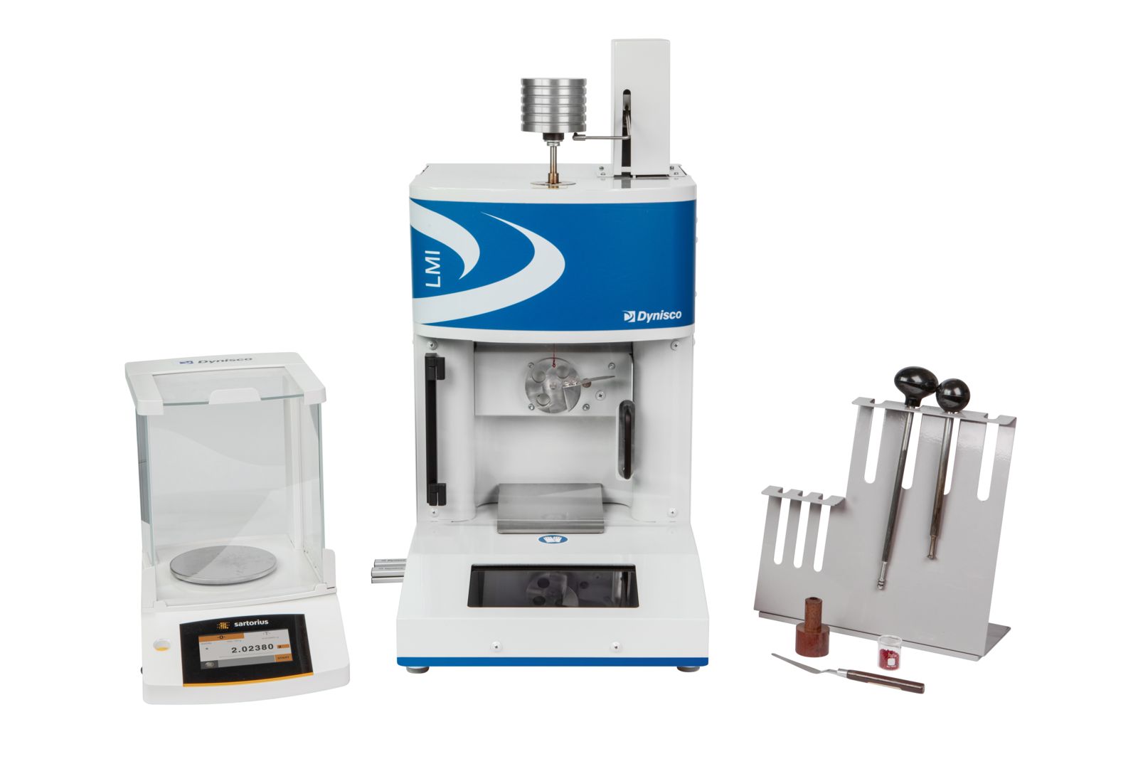
Dynisco LMI5500 Series, touchscreen extrusion plastometer compliant with ISO 1133-1/-2 and ASTM D1238, with automatic cutter for repeatable Procedure A cut-offs.
Higher automation
Dynisco LMI6000 Series, encoder-based displacement for Procedure B, weight-lift for staged loading and FRR runs, plus PET intrinsic viscosity.
Full viscosity curves
Dynisco LCR7000 capillary rheometer for shear-rate sweeps to ISO 11443, when single-point MFR cannot predict processing.
On-line rheology
Dynisco ViscoSensor for continuous melt viscosity monitoring on the extruder, correlated to laboratory MFR.
- Procedure A, B and combined A/B on one instrument, MFR, MVR and measured melt density from a single charge.
- Automatic timing and motorised cutting remove operator variation in cut-off length.
- FITCO India support: installation, training, calibration assistance, spares and nationwide service.
Specifications vary by configuration; contact FITCO India for a method package matched to your resins.
FAQs
What is the difference between MFR and MVR?
MFR is mass per 10 minutes (g/10 min); MVR is volume per 10 minutes (cm³/10 min). MVR is better for comparing filled with unfilled grades.
Should I use ISO 1133-1 or ISO 1133-2?
Part 1 for stable materials not sensitive to the test's time-temperature history. Part 2 for degrading or moisture-sensitive plastics.
How long is the ISO 1133 preheat?
Five minutes from completion of charging. Charging must finish in under one minute, and end of charging to last measurement must not exceed 25 minutes.
When can I use the half size die?
Above 75 g/10 min or 75 cm³/10 min, a die of 4.000 mm length and 1.050 mm bore may be used. No spacer may make up the length, and the report must say so.
Is ISO 1133 the same as ASTM D1238 and IS 13360?
IS 13360 (Part 4/Sec 1) is the BIS adoption of ISO 1133. ASTM D1238 is equivalent but not identical, preheat and procedure differ, so state the method used.
Need Help with ISO 1133 Melt Flow Testing?
Our experts can help you select the right Dynisco melt flow indexer, dies, weight sets and procedures for your resins, recyclates and quality-control throughput.
Specifying a machine for this standard?
Send the material, specimen geometry and expected force range. FITCO will recommend the frame, load cell, grips and extensometry, run your samples before you commit, and support installation, operator training and NABL-traceable calibration.