Master ISO 178: Flexural Properties of Plastics — Complete Testing Guide with Testometric UTMs | FITCO India

ISO 178 — Flexural Properties of Plastics

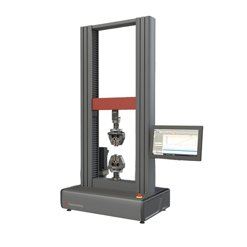
A complete, practical guide to three-point bending: span selection, deflection measurement, calculations, and reporting — built around Testometric UK universal testing machines and fixtures.

Standard: ISO 178 Updated: Aug 12, 2025 Reading time: ~12 min

Fixtures & span selection

Use a three-point bending fixture with two supports and a central loading nose. Support and nose radii should suit the material to minimize stress concentrations and surface damage.

  • Span-to-depth ratio: Select according to ISO 178 (commonly 16:1 or 20:1). Example: 4 mm thick → span ≈ 64 mm (16×).
  • Alignment: Ensure the loading nose contacts at midspan and supports are level and parallel; verify with a gauge block.
  • Low-friction supports: Help avoid shear from support drag, especially for thin or ductile materials.

Deflection & instrumentation

For modulus, measure midspan deflection directly with a deflectometer or high-precision displacement transducer. Video extensometry can also be used to track markers at midspan. Crosshead displacement alone may include system compliance and is less precise for modulus.

  • Load cell: Choose so test forces fall within 10–90% of rated capacity.
  • Deflection sensor: Mount per fixture instructions; zero under minimal preload.
  • Sampling: Capture data at a sufficient rate to resolve the linear elastic region and any yield or break events.

Strain rates & speeds

ISO 178 defines strain rate categories and corresponding crosshead speeds calculated from span, depth, and target strain rate. Program the machine to maintain the prescribed rate within tolerance.

  • Verify span and thickness inputs are correct before speed calculation.
  • Use a short preloading segment to seat the specimen on supports.
  • Confirm rate using a trial specimen and recorded deflection vs. time.

Quick setup checklist

Specimen

Dimensions verified (b, h), edges deburred, conditioned per ISO 291/material spec.

Fixture & span

Three-point fixture installed; span set to 16×/20× h; nose/support radii selected.

Deflection

Midspan deflectometer/video set up; zeroed under minimal preload; sampling rate set.

Method

Target strain rate programmed; preload defined; compliance correction policy noted.

Procedure

  1. Measure specimen width and thickness; compute average values.
  2. Set support span according to the chosen span-to-depth ratio.
  3. Install deflection sensor (or video setup) and verify zero.
  4. Apply preload to seat the specimen; zero load and deflection as required.
  5. Run at the programmed speed; record load and midspan deflection continuously.
  6. Stop at break or at the specified strain/deflection limit; save raw data and curve.

Calculations

Key outputs
  • Flexural stress and strain from measured load and deflection using ISO 178 formulas.
  • Flexural modulus from the slope of the initial linear region.
  • Flexural strength at yield or at maximum load.

Ensure you use the correct dimensions (width b, thickness h) and support span L. When computing modulus, select a strain interval entirely within the linear elastic region. Document the exact calculation method and any software options used.

Reporting

  • Specimen dimensions, conditioning, span, nose/support radii.
  • Deflection measurement method and location.
  • Programmed speed/strain rate, preload, and compliance corrections (if any).
  • Results: modulus, strength, strain, curves; n, mean, SD; outlier policy.
  • Instrument IDs, calibration dates, operator, and software version.

QA, verification & uncertainty

Establish a verification schedule for load, deflection, and speed. Use traceable references and document uncertainties. Run periodic proficiency checks and maintain locked test methods to prevent inadvertent changes.

Recommended Testometric setup

Frame & capacity

Testometric twin-column UTM sized so expected peak forces sit in the mid-range of the load cell for best resolution. High-stiffness frame aids modulus accuracy.

Three-point bend fixture

Adjustable-span, low-friction supports with interchangeable nose/support radii to suit material and thickness. Quick-change coupling to streamline setup.

Deflection measurement

Midspan deflectometer or video extensometry for precise modulus. Ensure proper seating, zeroing, and sampling rate.

Key platform advantages
  • ±0.5% system accuracy with 0.000001 mm position control resolution for tight flexural modulus.
  • High‑rate acquisition (500/1000 Hz) to capture yield/rupture cleanly.
  • Environmental chambers −165°C to +300°C; broad fixture/grip ecosystem.
  • FITCO India support: install, training, spares, after‑sales, 2‑year comprehensive warranty.

Model suggestions for ISO 178

Model (X‑Series)CapacityTypical use
X350‑1010 kNGeneral plastics flexural tests and education labs
X500‑2525 kNFilled/FR materials; larger spans and thicker sections
X500‑5050 kNHigh‑stiffness materials, composites, R&D fixtures
AccessoryOptionWhen to choose
Fixture3‑point bend with adjustable spanStandard ISO 178 testing; 16×/20× span rules
DeflectionMidspan transducerHighest precision modulus; low compliance
DeflectionVideo extensometerNon‑contact measurement; long‑span setups

Specs vary by configuration; contact FITCO for a calibrated ISO 178 method and accessory kit.

FAQs

How many specimens?

Many labs test ≥5 to enable robust statistics; follow your control plan or material spec.

What if the specimen slips?

Verify support cleanliness and alignment; check that the span and radii are correct and that loading is at true midspan.

When is crosshead displacement acceptable?

For strength endpoints where modulus isn’t required. For modulus, use midspan deflection.

Industries & materials

ISO 178 flexural testing is widely used in automotive, appliances, electronics, packaging, building products, and R&D labs to compare grades and verify performance. Materials include PP, PC, ABS, PA, POM, filled/FR variants, and composites. Select nose/support radii to avoid surface imprinting on softer grades.

Common pitfalls

  • Incorrect span-to-depth ratio causing non-representative stress/strain results.
  • Using crosshead displacement for modulus without accounting for system compliance.
  • Misalignment at midspan leading to torsion or uneven loading.
  • Support/nose radii too small, inducing surface damage.

Span planner (quick reference)

Pick a common thickness and see example spans for 16× and 20× rules of thumb. Always use the exact ratio required by your control plan, and report your actual L and h.

h = 2 mm
16×L = 32 mm
20×L = 40 mm
h = 3 mm
16×L = 48 mm
20×L = 60 mm
h = 4 mm
16×L = 64 mm
20×L = 80 mm
h = 6 mm
16×L = 96 mm
20×L = 120 mm
h = 8 mm
16×L = 128 mm
20×L = 160 mm